Alinghi 5 - from A to Zee
by JPJ - Sail-World on 28 Jul 2009
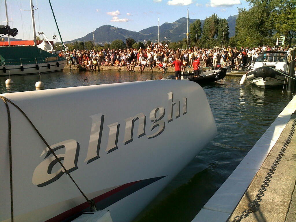
Alinghi 5 has plenty of admirers in le Bouveret Alinghi Team
www.alinghi.com
Sail-World's Swiss correspondent gives his impressions of the America's Cup Defender, Alinghi 5, launched just last week in le Bouveret:
Alinghi 5 has been out sailing four days now and although the wind hardly ever reach above 10 knots, we have a pretty good idea on the boat itself and how things work in its actual configuration, but please remember the Alinghi PR people have said: 'This is the first step in our development process towards defending the America' Cup next year'.
Let’s review the boat starting with a few design comments.
Alinghi 5 is the evolution of the 41ft catamaran dubbed 'Le Black' which was used some ten years ago on Lake Geneva, to be replaced by the Decision 35. That catamaran was used as a development and testing platform, the general design, in particular the Y shape that helps the front beam to support the compression load of the mast (pic 1).
Under the Y shape you can see a relatively complex assembly of struts and cables, these actually are needed to take up part of the compression load itself, this framework makes the whole platform rigid and compensates or counterbalances the stay loads as well.
They also used the old 40ft catamaran to test some ideas about the foils or boards that we now see on A5. The general shape of the Alinghi 5 hulls is also an evolution of the different catamarans you see in Switzerland, including the reverse bows.
Now remember that the design limitations is very simple, 90 feet LWL max (if one mast) and 90 feet maximum beam. The trim that we now see guaranties that the 90 feet LWL dimension is respected, this could explain why the boat looks like its to low at the stern - ergo a visible stern turbulence (pic 2).
This stern trim will be corrected for different reasons, one is that A5 will float higher in sea water, then the speed aspect will come in, including the use of the foils. More on that later. The hull(s) will plane somewhat and that should help, maybe some ballast aspect will also come into play. Rolf Volrijk when asked about the trim, quipped…'so many experts out there'. We do not have the precise dimensions but overall length must be around 110 to 115 feet, beam some 80 feet and mast head must be 170 feet above water. By the way, we do not know the total displacement and figures around five tonnes have been mentioned. The total load on the bottom of A5 masts is quite important and knowing that the mast weight only is around one tonne, the compression load can be estimated at several times that.
From bow to stern, let us review a few aspects of A5. as we have been able to observe them either at the dock or on the lake. By the way when ever needed/possible carbon fibre has been used to build the parts from the bowsprit to the wheels obviously including the hulls.
From the centre of the platform comes a long bow sprit that stands some 10 or 12 feet further than the hulls. At the end of that bowsprit, the flying big genoas are attached. (We have seen a reacher and a gennaker up to now). These are raised rolled up on themselves and there is a rolling/furling device mounted inside the end of the bow sprit, as they need to furl these big sails tacking or jibing because they have to pass in front of the forestay. These must be rolled up quite fast. The device is a hydraulic motor and it is superb in its efficiency (pic 3).
The forestay is fixed half way on that bowsprit just opposite of a dolphin striker which is part of the structure designed to take up the different loads, the tension on the forestay can be adjusted and that is done via a hydraulic ram which is hidden just under the bowsprit.
The two stays are sufficiently back from the mast (pic 4) so the mast is kept in place with these three main stays, the mast itself is some 160 feet long nearly three feet front to back and close to two feet thick, one man can actually stand in it to check it inside.
The design is deceptively simple: a big diamond with spreaders that are some six to seven feet long on each side, these spreaders (pic 5) are shaped so the jib would not chafe against them. The mast rests on a small rotula that is about the size of a tennis ball. It is rotating and the adjustment is made via two hydraulic rams connected to its base (pic 6).
The mast is raked backwards and the stays are attached to two metal rods that are the end of yet again two hydraulic rams. These would allow the mast to be modestly canted, although I have not seen it tested. There are also two running backstays, which are used while sailing. The end of these come back to winches.
The forestay can take different jibs and these are hoisted and not furled, the halyards are manned on the winches, either manually or, you guessed it, hydraulically. The No. 3 jib comes nearly at the base of the mast. For sure we will see other sails in the future.
The main sail has a noticeable square head; it is attached to the mast via cars and track. Its bottom is loose and is only attached to the end of the boom. The boom itself is controlled via a traveller on the rear beam, there is no main sheet as such, the end of the boom is connected to the traveller via a set up consisting of two hydraulic rams that are vertical, forming a V around the boom and bottom of sail (pic 7).
The rams outer fittings are connected to the boom. The rams’ internal parts connected to a fixed length of rope to the traveller. So the position of the boom is defined by the traveller and corresponding control to the winches, the final adjustment and tension to the boom, for example to flatten the mainsail, is done via the rams.
Close to the middle of the hulls are the boards or foils, these are very special and S shaped, they can be lowered and raised using a movable pole that props up to pull them up. When the board is down, the hoisting/lowering pole folds neatly down by the front beam. Various factors, sailing angle vs true wind, the wind speed and sea state can be taken into account to define which position of the board is best. The boards have marks to help selecting specific positions. The position will generate either lift vs a close hauled course or upward lift to diminish wetted surface or maybe both?
The whole area between the hulls and the beams has a big trampoline; the crew can pass from one hull to the other ducking under the Y beams. The helmsman will have to go from one hull to the other when tacking for example. There are three cockpits in each hull, the front is the trimmers’ cockpit, the second is the helmsman’s and the third is the tactician’s cockpit.
The wheels are as big as the cockpit allows but not big in reference to the boat itself. They drive via cables the quadrant on the rudders’ axis, then there is a set of carbon poles that link the two rudders, and the central link slides on cars in the back of the rear beam. Therefore when you turn one wheel; it actuates the rudder which in turns moves the link to the other rudder and wheel, elegant. An simple and elegant solution which looks light to the touch in relation with the size of A5.
Last but not least, the infamous engine sported on the centre of the rear beam, that engine drives pumps and ventilators in relation to the different hydraulic system on board A5. Is there direct pumps connected to the engine or electric pumps driven via a alternator? Hard to tell.
The engine control must be connected to the demands of the hydraulic system and its revs should vary accordingly. If the bowsprit furling device is the most elegant technological part of the design, be it a totally built from scrat
If you want to link to this article then please use this URL: www.sail-world.com/59496